

Categories
You must follow essential piping requirements for a 120 ton split air chiller with dual semi-hermetic screw compressors and R513A refrigerant. You must execute exact line sizing, correct liquid lines diameter, velocity control for oil return, subcooling targets, and proper trapping. Precise pipe installation prevents compressor damage, flash gas, severe capacity loss, and sudden pressure drops. Poor pipe layout creates documented failure modes:
Overstressed fittings and branch connections at penetrations
Support failures or cracked anchors during temperature changes
Excessive nozzle loads causing gasket leakage or exchanger plate pack issues
Fatigue failure at small-bore connections during frequent thermal cycling
Strict engineering design protects your air Cooled Screw Chiller system.
Control refrigerant speed in pipes to keep oil moving and protect the chiller compressors from damage.
Install double risers and oil traps to keep oil flowing properly during partial-load operations.
Slope horizontal pipes downward to help gravity pull oil back toward the main compressor sumps.
Insulate cold lines and add vibration dampeners to prevent energy loss and stop pipe leaks.
Purge copper pipes with nitrogen during brazing to block harmful scale from ruining internal parts.
Designing the suction line of a 120 ton industrial split air chiller requires strict engineering attention and precise line layout. You must maintain proper suction gas velocities to guarantee continuous oil return to the dual semi-hermetic screw compressors. Incorrect refrigerant suction line sizing drastically reduces system efficiency, lowers net cooling capacity, and causes severe compressor failure over time.
You must control the velocity of returning refrigerant gas within tight operational limits. Entrained compressor oil travels along the inner walls of the suction pipe together with the gaseous medium. Low gas speeds allow lubricating oil to settle inside horizontal copper runs and vertical risers. Settled oil starves the compressor sumps, causing mechanical friction and costly component failure. Conversely, excessive gas speeds create an unacceptable head loss, reducing overall refrigeration cycle performance.
You must adhere strictly to established industry velocity standards to maintain constant lubricant movement throughout the suction line:
|
Line Orientation |
Minimum Velocity |
Maximum Velocity |
Primary Engineering Purpose |
|---|---|---|---|
|
Horizontal Runs |
1,000 fpm |
1,500 fpm |
Prevents oil pooling while minimizing line friction |
|
Vertical Risers |
1,500 fpm |
2,200 fpm |
Overcomes gravity to carry oil upward to compressors |
Maintaining these exact velocity ranges guarantees reliable oil return during full-load operation. However, total suction line pressure drop must remain minimal across all horizontal pipe runs and vertical risers. Excessive suction line resistance lowers saturated suction pressure, forcing the dual screw compressors to consume extra electrical power. You must size suction piping carefully to balance oil transportation against unacceptable friction losses.
Industrial cooling demands fluctuate significantly based on ambient weather conditions and factory process loads. A 120 ton air cooled chiller frequently operates under partial load by staging its dual compressors. Reduced refrigerant mass flow lowers gas velocity inside suction lines. Standard single-pipe vertical risers fail to transport lubricating oil upward during these low-capacity operating periods.
You must install a double-riser assembly to satisfy dynamic part-load velocity requirements. An engineered double-riser configuration consists of two parallel vertical lines: a smaller primary riser and a larger secondary riser. An inverted trap connects the secondary riser at the upper discharge point, while a deep oil trap sits at the bottom junction.
During full-load operation, refrigerant vapor flows freely through both vertical lines. The combined cross-sectional area accommodates full vapor flow without generating excessive friction drop. When the system operates under partial load, reduced refrigerant volume cannot maintain the required 1,500 fpm velocity through both open risers. Oil collects inside the lower trap, effectively sealing off the larger secondary riser.
This oil seal diverts the entire reduced gas volume into the smaller primary riser. The reduced cross-sectional pipe area boosts vapor velocity above the critical 1,500 fpm threshold. The rising gas successfully sweeps entrained oil upward to the air Cooled Screw Chiller suction manifolds. When the system returns to full cooling capacity, increased suction pressure clears the oil seal. Both risers automatically resume normal operation without external valve controls. Following these precise suction line requirements guarantees long-term system reliability and stable oil management across all operating conditions.
You must execute precise sizing liquid lines for the OUMAL split air chiller. The OUMAL system utilizes two completely independent refrigeration circuits to serve its dual screw compressors. Dual circuits isolate each refrigeration loop, preventing a mechanical issue in one circuit from affecting the other. Correct line sizing keeps velocity high while minimizing friction losses along copper runs.
You need sufficient subcooling to protect long liquid lines against static pressure loss and premature vaporization before the expansion device. Friction loss inside long pipe runs lowers static fluid pressure. When total pressure drop exceeds subcooling margins, liquid refrigerant boils instantly, creating unwanted flash gas. Flash gas drastically reduces thermal expansion valve capacity, starves the evaporator coil, and lowers total cooling output.
At low evaporating pressures, suction gas density drops, refrigerant mass flow decreases, temperatures plummet, and oil viscosity climbs sharply. That combination means the refrigerant vapor carrying oil back through the suction line loses momentum fast. Without adequate vapor velocity — roughly 700 ft/min in horizontal runs and 1,500 ft/min in vertical risers — miscible oil and refrigerant mixtures stratify, and oil pools in evaporator coils, suction line traps, and low spots instead of returning to the compressor crankcase.
Maintaining proper fluid velocity and subcooling prevents operational failures under varying ambient temperatures. The dual-circuit architecture of the 120 ton air cooled chiller ensures each circuit retains adequate mass flow during partial-load conditions.
|
Configuration Aspect |
Dual-Circuit System |
Single-Circuit System (at half capacity) |
Impact on Oil Return & Distribution |
|---|---|---|---|
|
Circuit Independence |
Two independent compressors and circuits. |
Single circuit serving the full coil. |
Dual circuits prevent one failure from affecting the other's oil return. |
|
Refrigerant Flow at Part Load |
Active circuit maintains required mass flow. |
Full coil carries half the mass flow. |
Velocity drops significantly in single circuits, risking compressor failure. |
|
Suction Line Velocity |
Maintains designed velocity in active pipe runs. |
Velocity drops to half of full-load design. |
Low velocity (<1000 fpm for risers) fails to carry oil back to compressor. |
Proper component selection and installation guarantee clean fluid delivery to metering components across your industrial system. You must install a heavy-duty moisture filter-drier in each independent circuit. Place the filter-drier in the horizontal liquid pipe segment close to the condensing unit outlet. This position traps solid debris, construction scale, and moisture before fluid reaches expansion valves or shell-and-tube evaporator circuits.
Position a moisture-indicating sight glass directly downstream of the filter-drier. The sight glass provides a clear visual indication of liquid condition. Continuous solid fluid flow through the glass proves full subcooling, whereas persistent bubbles indicate flash gas or low refrigerant charge. You must follow four explicit piping requirements during system setup:
Target 1,500 feet per minute (fpm) in vertical risers and 700 fpm in horizontal runs to keep oil entrained in the refrigerant vapor stream.
Pitch horizontal pipe runs toward the compressor at ½ inch per 10 feet to eliminate low spots where oil can pool.
Install P-traps at every riser base, adding extra traps every 20 feet of rise when compressors sit above evaporators.
Verify all pipe connections meet strict code engineering requirements before charging system circuits.
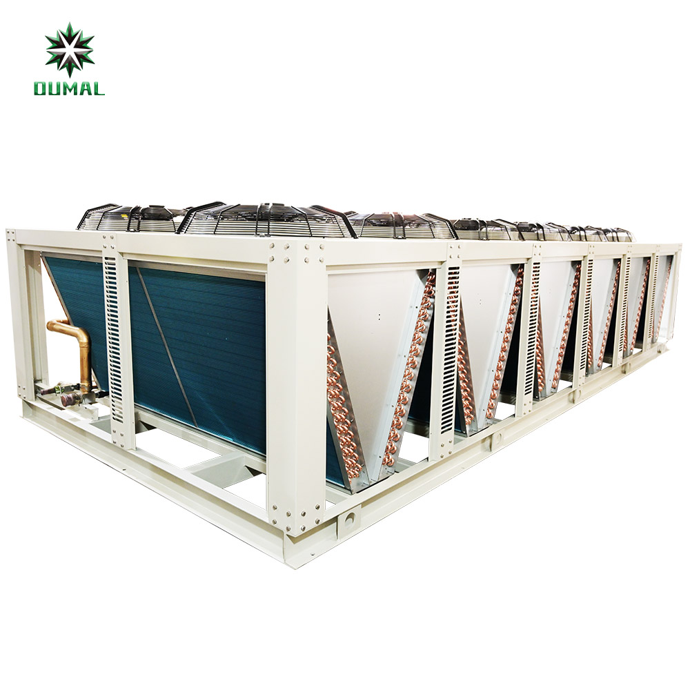
You must install hot gas discharge risers carefully when connecting compressors to outdoor condensing assemblies. The discharge line carries high-temperature refrigerant gas together with atomized oil. Vertical risers require adequate gas velocity to transport this oil upward against gravity. Without proper traps, oil settles inside the discharge pipe during compressor shutdowns and creates heavy hydraulic shocks upon restarting.
You must place a trap at the base of every vertical discharge line. Furthermore, vertical elevation changes demand periodic intermediate trapping along the vertical pipe run.
Because the refrigerant-oil mixture will gradually lose velocity as it climbs, a basic guideline is to install an oil trap every 10–15 feet, depending on the system designer.
You must keep trap depth under 4 times the outside diameter of the pipe. Matching the trap pipe size directly to the main run prevents velocity drops. These strict piping requirements protect your compressors against oil starvation.
You must execute split system line sizing with extreme precision to limit total system pressure drop. Long line runs increase internal friction, forcing compressors to work much harder. Contractors report systems losing up to 15 percent of rated cooling capacity due to excessively long line sets. Excessive length increases head friction, which boosts overall electrical energy consumption.
Manufacturers cap vertical elevation separation between 15–50 feet depending on equipment layout. Every foot of vertical rise alters static liquid pressure inside the line set. Loss of pressure allows hot liquid refrigerant to vaporize prematurely before reaching metering devices.
Proper field installation requires sloping horizontal pipe runs at least ½ inch per 10 feet toward the trap. This slope uses gravity to move entrained oil continuously through each split air chiller circuit. Following these physical requirements guarantees reliable oil return and maintains maximum operational efficiency.
Executing a successful refrigerant pipe installation requires strict control over clean copper joining techniques and physical line slope. You must protect internal line sets during assembly to maintain system reliability for your 120 ton split air chiller.
You must displace internal oxygen during silver-alloy brazing of R513A lines and shell-and-tube heat exchangers. Heating copper pipes in the presence of air generates scale, which clogs internal filter-driers and destroys compressor bearings.
Mandatory procedure: For critical applications such as HVAC/R systems, purging the interior of the system with an inert gas (typically nitrogen) during brazing is mandatory. This displaces oxygen, preventing the formation of internal oxides (scale) that can contaminate the system, restrict flow, and damage components like compressors.
You can prevent poor joint quality and internal copper flaking by using proper nitrogen controls:
Run dry nitrogen at a low, steady flow through refrigerant lines before brazing begins.
Maintain the nitrogen flow continuously during the entire brazing process to prevent internal oxidation.
|
Source |
Recommended Flow Rate |
Recommended Pressure |
Key Guidance |
|---|---|---|---|
|
HVAC Training Solutions / ACHR News |
2-3 CFH (Cubic Feet per Hour) |
1.5 – 2 PSI |
Use low volume/pressure to displace oxygen. Avoid excessive flow that builds internal pressure or cools the tube. Initiate flow before heating and continue until cooled. |
|
Chads AC Direct |
2 to 5 SCFH (Standard Cubic Feet per Hour) |
Not specified (set for a faint hiss) |
A steady, gentle flow is key—enough to displace oxygen but not a rush of air. |
You must slope horizontal gas piping 1/2 inch per 10 feet toward the flow direction. Proper pitch uses gravity to return oil to the dual screw compressors.
You must cover all suction liquid lines with closed-cell elastomeric pipe insulation. Proper insulation thickness prevents condensation drip and stops line energy loss. You must insulate cold pipe surfaces continuously without gaps.
Heavy dual screw compressor discharge outlets generate strong pulses. You must install flexible vibration eliminators near outdoor compressor connections. Proper vibration isolation minimizes acoustic transfer, relieves mechanical stress, and prevents pipe fatigue. Following these physical installation requirements protects your air Cooled Screw Chiller system against leaks.
You must satisfy strict piping requirements for your 120 ton split air chiller to reach full rated efficiency. Execute exact field installation practices using these design requirements:
Velocity Limits: Maintain 1,000–1,500 fpm in horizontal pipe runs and 1,500–2,200 fpm in vertical risers.
Pressure Control: Minimize total suction line pressure drop to preserve capacity, and keep liquid pressure high to avoid flash gas.
Pipe Insulation and Pitch: Apply continuous closed-cell elastomeric insulation, and slope horizontal gas pipe runs ½ inch per 10 feet.
Elevation Constraints: Limit total vertical elevation changes between 15 and 50 feet.
Precise line execution protects your air Cooled Screw Chiller from damage while guaranteeing long-term reliability.
You must satisfy strict velocity requirements between 1,500 and 2,200 fpm in vertical risers. This velocity carries entrained lubricating oil upward to the dual semi-hermetic screw compressors. Lower gas speeds allow oil pooling, while higher speeds cause excessive suction pressure drops.
You must slope horizontal lines at least ½ inch per 10 feet toward the flow direction. This pitch uses gravity to move entrained oil directly to compressor sumps. Proper sloping prevents liquid oil from settling inside horizontal runs during partial-load operating periods.
Manufacturers cap vertical elevation separation between 15 and 50 feet. Excessive vertical rise causes static pressure loss in liquid lines, creating unwanted flash gas. You must follow these height limits to preserve total cooling capacity across your 120 ton split air chiller.
You must purge dry nitrogen at low pressure during silver-alloy brazing. Nitrogen displaces oxygen inside copper lines, preventing harmful scale formation during installation. Eliminating internal copper flaking protects filter-driers and air Cooled Screw Chiller compressor bearings from premature mechanical failure.



Friendly Links :
www.dyyseo.com en
en es
es